

 English
 Español
News
Home / News / Solenoid Valve Solutions / How to Install a Solenoid Valve: Complete Step-by-Step Guide
News
Content
Installing a solenoid valve correctly ensures reliable operation, prevents leaks, and extends service life by up to 10 years. The process involves mounting the valve in the proper orientation, connecting inlet and outlet lines, wiring the electrical coil, and testing for leaks. Most installations take 30-60 minutes with basic tools.
Before installation, verify that your solenoid valve matches system requirements. Check the following specifications:
Gather these items before beginning installation:
The solenoid coil must be positioned vertically upward in most installations. This orientation prevents debris accumulation and ensures proper operation. Studies show that incorrect mounting reduces valve lifespan by 40-60%.
| Mounting Position | Acceptable | Impact on Performance |
|---|---|---|
| Coil Vertical (Upward) | Yes (Recommended) | Optimal performance and longevity |
| Coil Horizontal | Check Specifications | May cause premature failure |
| Coil Downward | No | Debris accumulation, reduced lifespan |
Locate the flow direction arrow stamped on the valve body. Install the valve so this arrow points in the direction of fluid flow. Reversed flow direction can cause complete valve failure or reduce flow capacity by 30-50%. Mark the inlet side clearly during installation to prevent future confusion.
For NPT or BSP threaded connections, follow this procedure:
For larger valves with flanged connections, ensure gasket material matches the operating temperature and pressure. Torque bolts in a star pattern to 25-30 ft-lbs for 2-inch flanges, increasing proportionally for larger sizes. Welded connections require certified welders and post-weld pressure testing.
Install a strainer or filter upstream of the solenoid valve to protect internal components. Position the filter within 12 inches of the valve inlet. This simple addition extends valve service life by 3-5 years in systems with particulate contamination.
For AC-powered solenoids, follow these safety protocols:
DC solenoids are polarized and must be wired correctly. The red wire typically connects to positive, and black to negative. Reversed polarity prevents operation and may damage the coil. Use a multimeter to verify voltage and polarity before final connection. Install a flyback diode across the coil terminals to suppress voltage spikes when the valve closes.
When connecting to PLCs, timers, or microcontrollers, use appropriate relays or solid-state switches rated for the coil's inrush current, typically 2-3 times the holding current. For a 10-watt coil at 24V DC, the initial draw may reach 1.2 amps before settling to 0.4 amps.
Before energizing the valve, perform these checks:
Energize the solenoid and verify operation:
Ensure system pressure meets the valve's minimum differential pressure requirement, typically 0.5-2 PSI for pilot-operated valves. Insufficient pressure differential causes slow closing or incomplete sealing. Install pressure gauges on both sides of the valve during commissioning to verify proper operation.
Excessive torque cracks valve bodies, especially in brass models. Field data shows that 65% of premature valve failures result from installation stress. Use torque wrenches for critical applications and never exceed manufacturer specifications.
Direct-acting solenoids work from 0 PSI, but pilot-operated valves require minimum pressure. Installing a pilot-operated valve in a gravity-fed system with 0.2 PSI will cause failure. Check valve specifications and select the appropriate operating principle for your application.
Undersized wiring causes voltage drop, preventing proper valve operation. For a 24V DC valve drawing 0.5 amps over 50 feet, use minimum 18 AWG wire. Calculate voltage drop: a 10% voltage drop reduces closing force by 20%, leading to incomplete sealing.
Many solenoid valves include manual override buttons. Test this feature during installation to verify mechanical function independent of electrical operation. This confirms the valve internals are functioning correctly before troubleshooting electrical issues.
Diagnose using this systematic approach:
For persistent leaks after tightening, drain the system, disassemble the connection, inspect threads for damage, and reapply sealant. Thread damage accounts for 30% of leak issues in field installations. Replace damaged components rather than attempting repairs.
Chattering or buzzing indicates AC coil issues, voltage fluctuation, or water hammer. Install pipe supports within 6 inches of the valve to minimize vibration. For water hammer, add an expansion tank or water hammer arrestor upstream. AC valves may buzz at 10-15 decibels; DC valves should operate silently.
Implement this maintenance schedule for optimal performance:
For outdoor installations, use NEMA 4X rated coils and junction boxes. Apply dielectric grease to electrical connections to prevent corrosion. In freezing climates, install heat trace cable or drain valves in low points. Proper environmental protection extends service life from 5 years to 15+ years in harsh conditions.


Copyright © 2025 Alahot (zhejiang) Technology Co., Ltd.
All Rights Reserved.
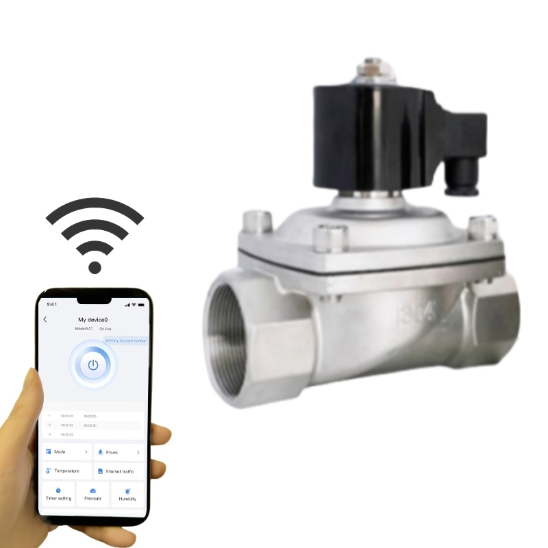
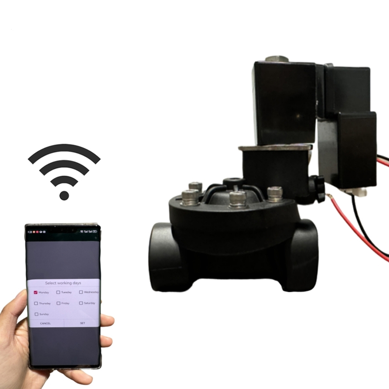
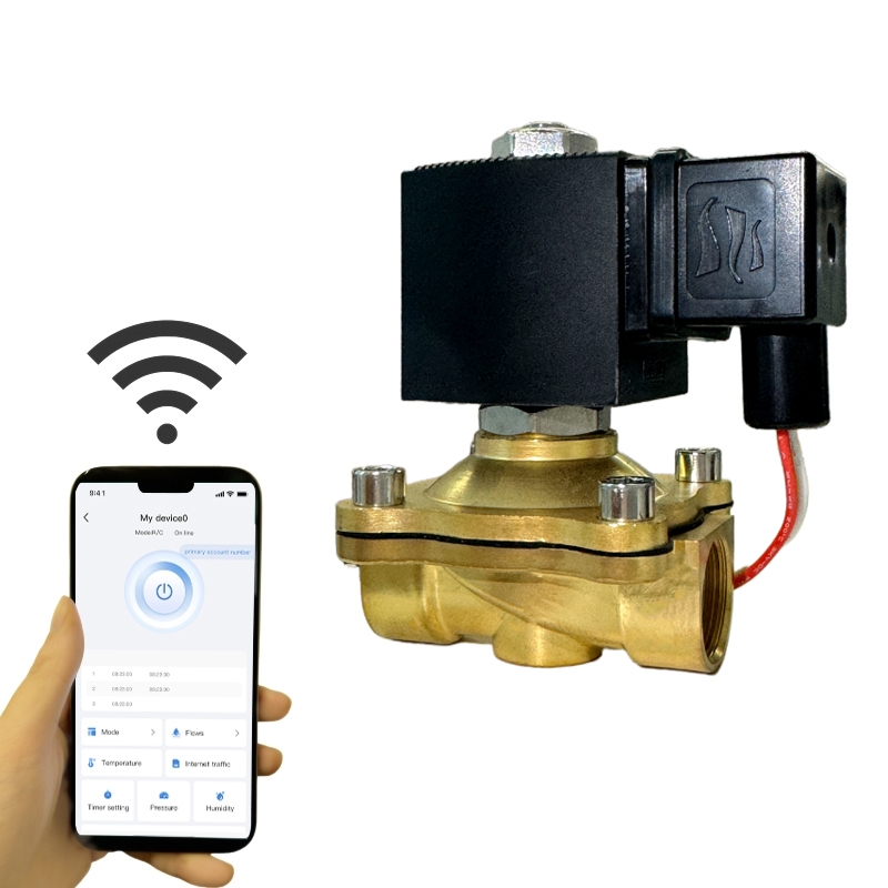
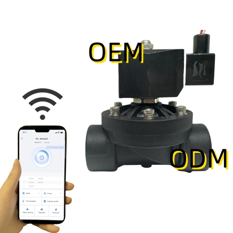
OEM/ODM Electric Solenoid Valves Manufacture
