


 English
 Español

News
Home / News / Solenoid Valve Solutions / Latching Solenoid Valves: How Zero-Power Holding Works and How to Specify
News
Content
The valve remembers its last command. The coil works only during a state change, so thermal load and standby battery drain drop sharply.
A latching solenoid valve separates actuation from holding, while a standard solenoid valve must keep current flowing to stay open or closed. In a standard direct-acting or pilot-operated valve, the coil produces holding force continuously. In a latching design, a pulse moves the plunger and a permanent magnet takes over.
| Behavior | Continuous-duty solenoid | Latching solenoid |
| Holding current | Coil energized for the full open or closed period | No holding current after the pulse |
| Coil heat | Continuous thermal load, especially in small enclosures | Heat only during the pulse |
| Control wiring | Simple on/off output, often two wires | Pulse or polarity control, or an integrated reset circuit |
| Last state | Returns to spring or pilot state when power is lost | Holds the last commanded position |
| Best fit | Frequent cycling with available mains power | Battery, solar, remote, or low-heat applications |
A latching solenoid valve is a bistable solenoid valve that uses a permanent magnet to hold the plunger in its last position, so the coil only needs a pulse to change state.
The practical result is less heat in the coil, lower standby load on batteries, and a valve that can stay in position through long irrigation cycles, remote shutdowns, or intermittent dosing events. The tradeoff is that control electronics must deliver a defined pulse, and the valve must be selected for the medium and pressure at that pulse.
A short pulse changes the magnetic circuit; the permanent magnet keeps the plunger seated until the next command. The sequence is mechanical and electrical at the same time, which is why pulse shape matters as much as coil voltage.
The control board sends a pulse to the coil. Pulse length is usually set by the valve datasheet or by an integrated reset circuit.
Magnetic force must overcome spring force, seal friction, and line pressure before the plunger reaches the end stop.
At the end of the stroke, the permanent magnet captures the plunger and holds it without coil current.
The next pulse, often with reversed polarity in a bistable design, releases the plunger and changes the valve state.
The coil is an actuator, not a heater. It does work only during the state change, and the magnet does the holding.
Bistable latching valves change state with a pulse and often need polarity reversal to return. Integrated reset types add local electronics so a single input can toggle, reset, or time the valve without the host controller carrying the full drive logic. For a design review of pulse shaping and hold-force budgets, the zero-power latching solenoid valve technology white paper is a useful reference.
Latching valves are strongest where power is scarce, heat is unwanted, or a valve must hold position through long idle periods. They are not automatically the best choice for every line; the application has to accept pulse control and a defined last state.
Long idle periods make holding current the dominant battery load. A pulse valve can run from a small solar or battery pack.
Zone valves open for hours. Removing holding current reduces coil heat near controls and saves standby power.
Shows need repeatable on and off timing. Latching valves hold the last scene state if power drops.
A defined last state can be useful for deluge or isolation, but code and fail-safe requirements must be confirmed.
Pulse operation fits batch dosing and remote shutoff where continuous coil power is not available.
Replacing continuous coils can cut panel load, but check controller output, cable polarity, and diagnostics.
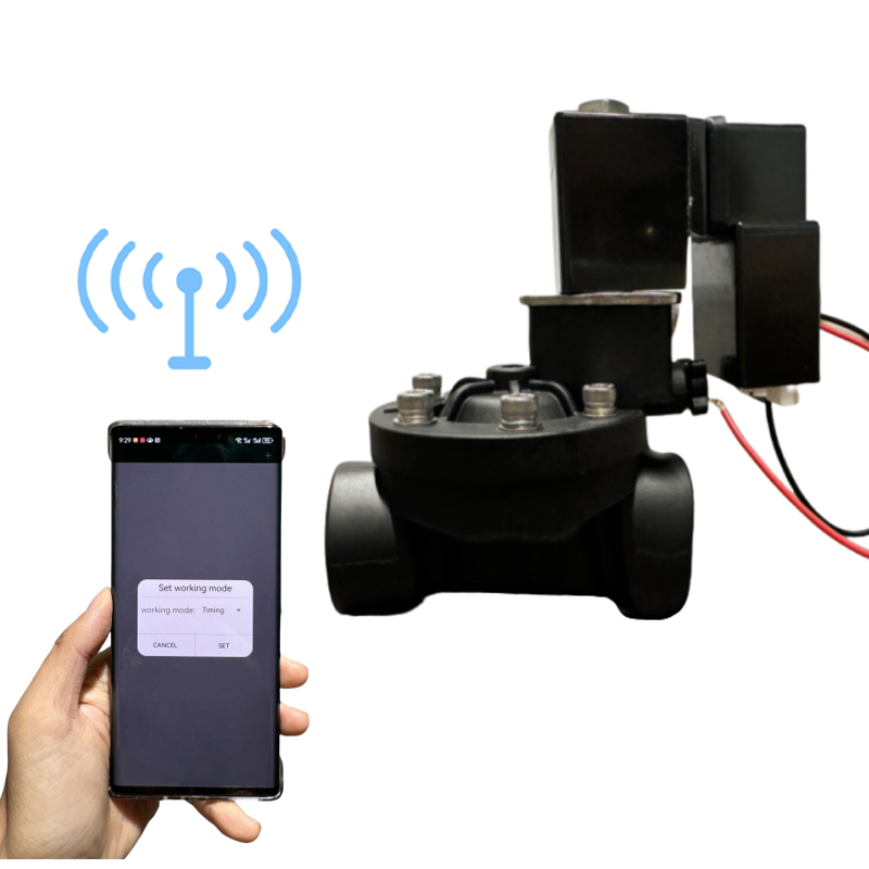
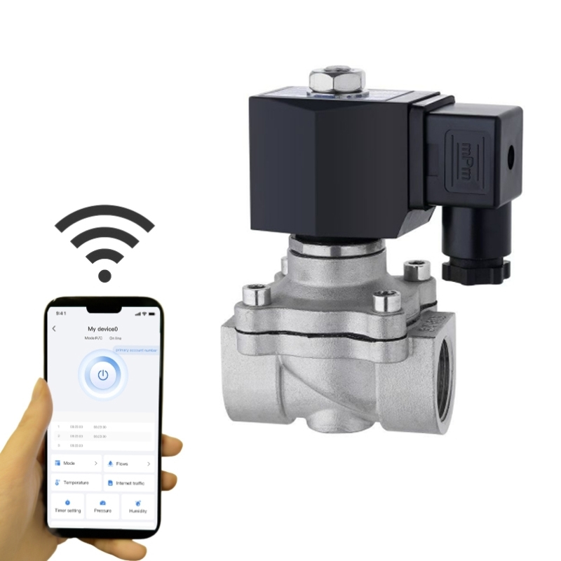 Plastic Latching Solenoid Valve for Low-Power ReplacementLow-power auto-reset latching valve with DIN43650 plug-and-play installation, below 0.05 W DC holding, and no external driver; check controller output and cable polarity.View Product →
Do not treat zero holding power as zero design work. Pulse energy, coil resistance, cable length, and capacitor size still set the electrical budget for each shift.
Start with five numbers: pulse voltage, pulse duration, coil resistance, line pressure, and required flow at pressure drop. If any one is missing, the valve may shift on the bench and fail in the field.
| Specification | Why it matters | Practical check |
| Pulse voltage | Too low a pulse leaves the plunger short of the magnet; too high a pulse stresses the coil. | Confirm voltage at the coil with cable length and temperature included. |
| Pulse duration | The coil needs enough time to complete the stroke against pressure and friction. | Measure current and movement at the lowest expected temperature. |
| Coil resistance | Resistance sets current draw and heat for a given pulse voltage. | Check the value at the expected coil temperature, not only at room temperature. |
| Line pressure | Pressure can aid or oppose the plunger, depending on valve design. | Test at maximum and minimum operating pressure, not just the nominal point. |
| Flow at pressure drop | Thread size does not guarantee flow through the orifice. | Compare flow curves at the actual pressure drop and media viscosity. |
A latching valve is a system component, not a drop-in coil swap. The controller, cable, valve, and fluid path must be checked together.
Do not size from pipe thread alone. A 1/2-inch valve with a restrictive orifice can miss the flow target, and a valve with extra spring or seal friction can need a longer pulse than the catalogue value. Ask for pulse current at the expected coil temperature and confirm the controller can deliver it through the installed cable.
Material choice is a wetted-path and installation decision, not a cosmetic one. The same latching mechanism can sit behind brass, engineering plastic, or stainless steel, but the seal, thread, and pressure rating change with the body.
Brass suits neutral water and many non-aggressive fluids at moderate pressure. Check dezincification risk in soft or aggressive water, and confirm the seal elastomer for the actual medium.
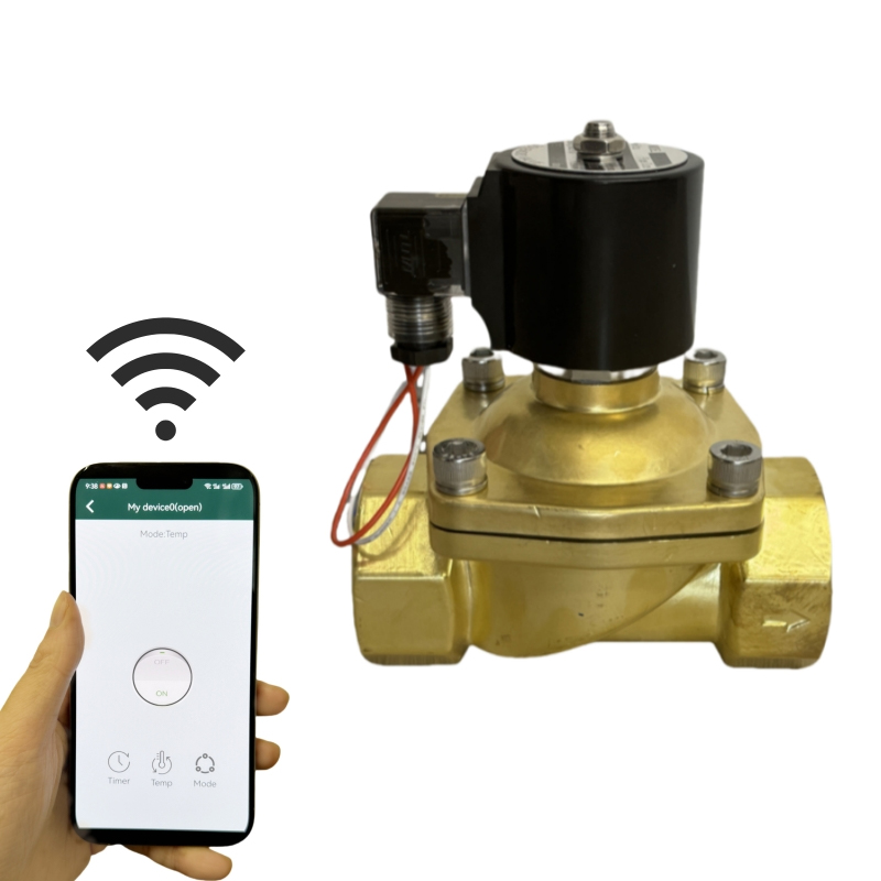
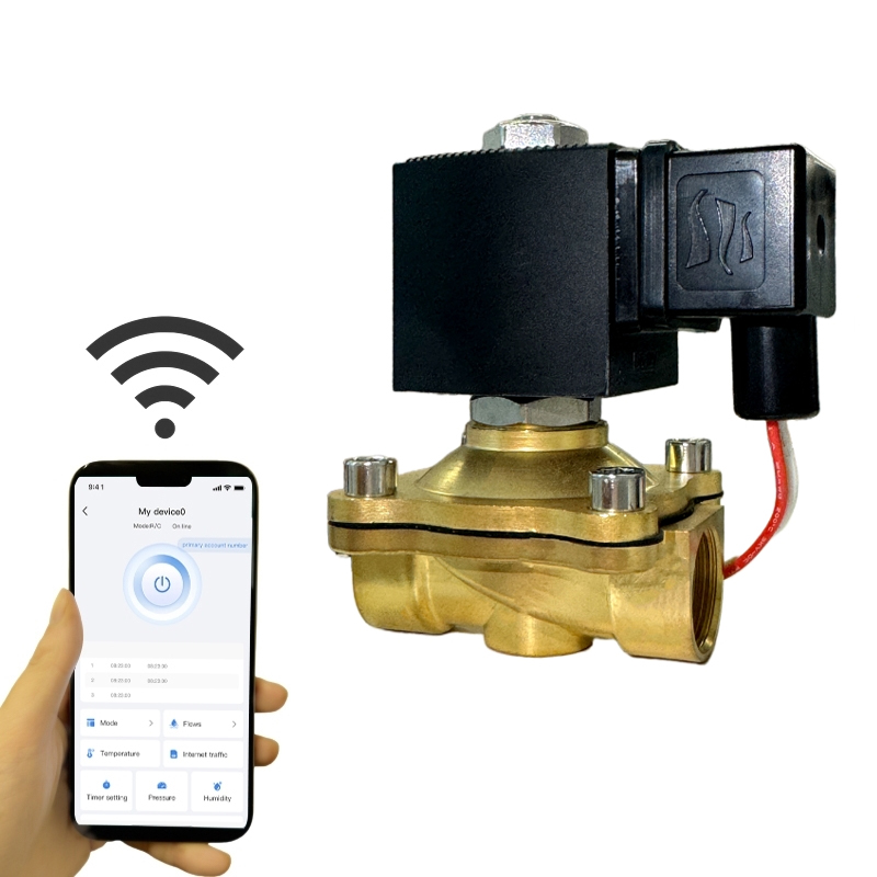
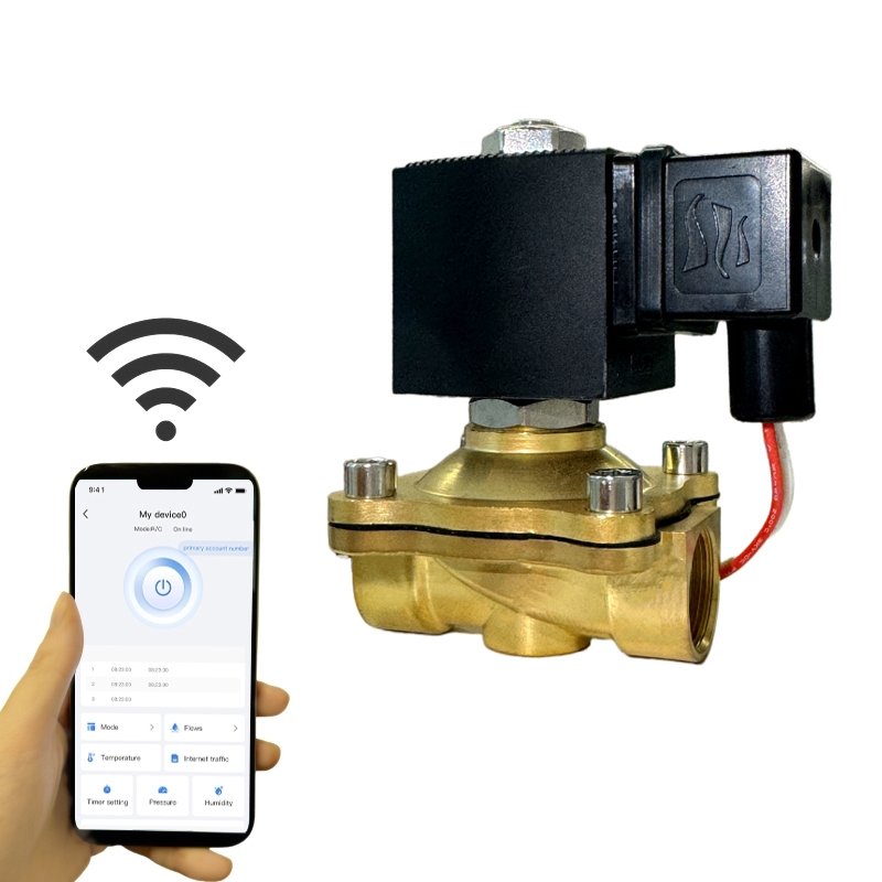 Brass Pulse Solenoid Valve for Low-Power Fluid ControlBrass latching/pulse valve with universal wiring, DIN43650 interface, and below 0.05 W DC holding; verify dezincification risk and seal elastomer for the medium.View Product →
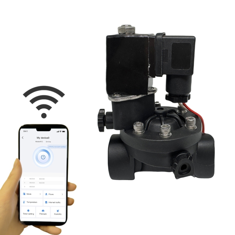
Plastic bodies fit battery irrigation, light-duty dosing, and portable equipment where weight and corrosion resistance matter. Verify UV exposure, thread strength, and support on long pipe runs.
Stainless steel is the starting point for higher pressure, aggressive media, washdown areas, and outdoor installations that need a stronger body. Confirm the seal compound and the pressure rating at the target temperature.
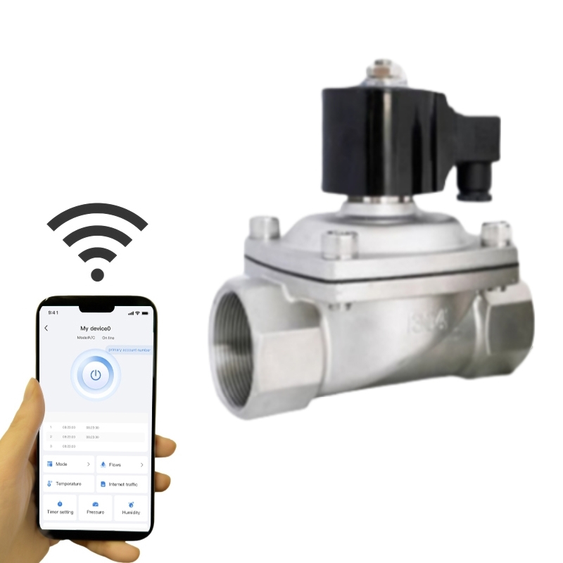
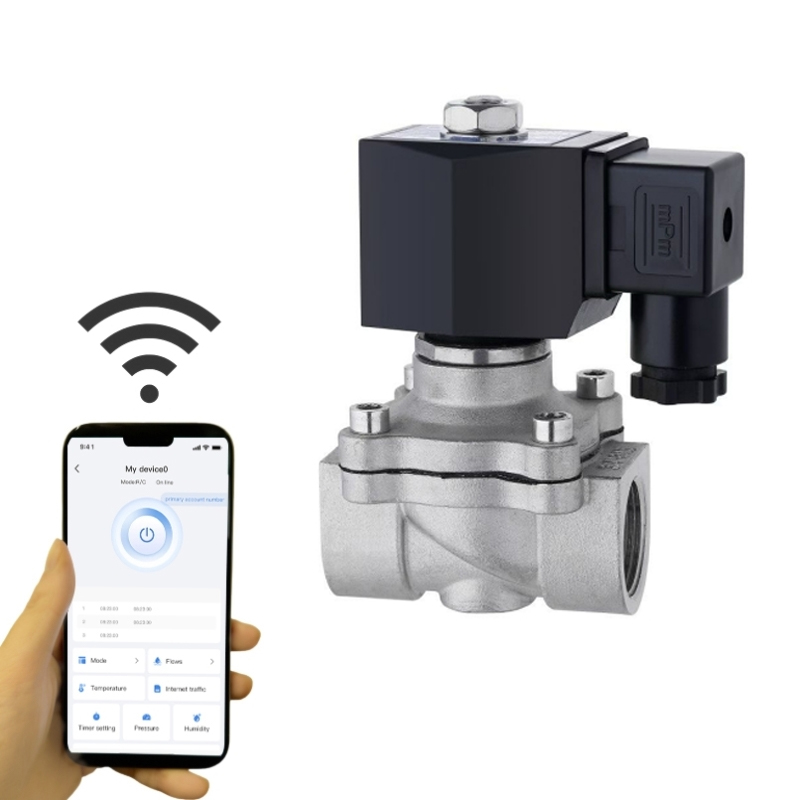 Stainless Steel Pulse Solenoid Valve for Demanding MediaSS304 latching/pulse valve for short energizing and long actuation; confirm seal compound and pressure rating at target temperature before specifying in aggressive or washdown service.View Product →
Specify the seal, not just the body. A brass valve with the wrong elastomer can fail faster than a plastic valve with the right one.
Most latching valve complaints trace to pulse energy, polarity, debris, or seal friction, not to the permanent magnet. The magnet is passive; the control and the fluid path are the active variables.
A valve that holds position is not the same as a valve that fails safe. Define the required last state for power loss, controller reset, and maintenance before choosing a latching design.
These are the questions engineers and buyers ask most often when comparing latching valves with continuous-duty solenoids.
No, a bistable latching valve does not need holding current after the pulse. It uses a permanent magnet to keep the plunger in position, so standby power is near zero apart from any control electronics.
A standard bistable latching valve fails in its last state because the magnet holds the plunger. If the application needs a defined closed position on power loss, specify a spring-return or reset arrangement and confirm the failure mode with the supplier.
Use the shortest pulse that reliably shifts the valve at the lowest expected temperature and pressure, then add a small margin for cable and coil tolerance. A pulse that is too short causes missed shifts; a pulse that is too long adds heat without improving holding force.
They can be, but debris is less forgiving in a latching design because the plunger must complete its stroke to reach the magnet. Use filtration, choose a direct-acting or pilot design that matches the debris risk, and test with the actual media.
Match the valve to the pulse, the media, and the required last state. Zero holding power is valuable only when the full control loop can deliver a reliable shift every time.



Copyright © 2025 Alahot (zhejiang) Technology Co., Ltd.
All Rights Reserved.
OEM/ODM Electric Solenoid Valves Manufacture
