


 English
 Español
News
Home / News / Solenoid Valve Solutions / Zero-Power Integrated Reset-Type Latching Solenoid Valve: A Technical Guide for the Water Sector
News
Content
A mid-sized municipal water system may operate hundreds of solenoid-actuated valves across pump stations, filtration lines, District Metered Areas (DMAs), and remote pressure-regulating stations. Most of these are conventional monostable, direct-acting valves — the coil must stay energized continuously to hold the open or closed position. Take a typical DN25 water solenoid valve as an example: coil power usually runs 8–15W, and the standby electricity cost of hundreds of such valves running year-round often accounts for more than 15% of a site's operating costs, while the constant heat buildup inside control cabinets also shortens the lifespan of nearby electronic components.
This is the gap the Zero-Power Integrated-Reset Latching Solenoid Valve is designed to fill. Instead of keeping the coil energized to hold position, it relies on the magnetic latching force of a built-in permanent magnet to mechanically lock in place after a single pulse — and holds that state without drawing any meaningful current.
Understanding the value of this valve starts with three core mechanisms:
Permanent magnets are embedded at both ends of the valve spool, forming an asymmetric magnetic circuit. When the coil applies a forward or reverse pulse (typically 50–100ms), the electromagnetic flux combines with the permanent-magnet flux to drive the spool to its fully open or fully closed position. Once there, the holding force of the permanent magnet "latches" the spool in place, and the coil is then fully de-energized.
Based on the integrated electronic drive module, measured standby power draw can be as low as <5mW DC (including the drive circuit's static loss), with the mechanical holding stage approaching zero power consumption.
Conventional solenoid valves follow continuous-power-matching logic: a coil rated at 12W requires a power supply that continuously delivers ≥12W, cable cross-sections are sized for 12W of heat dissipation, and switching power supplies are sized by 12W × the number of valves.
The zero-power integrated reset-type latching solenoid valve uses pulse-energy-matching logic instead: the coil's instantaneous power is 12W (needed to establish the magnetic field) for only the brief pulse duration. Through an integrated boost-and-store design, the drive module needs only 2.4W of average supply power to "accumulate" enough energy for one pulse. At rest, standby draw is <5mW — essentially no power is drawn at all.
This means power supply ratings, cable cross-sections, switching power supply capacity, and transformer margins can all be sized around average pulse power rather than cumulative continuous power. Power supply configuration costs can be reduced by more than 80%.
This is what sets it apart from an ordinary bistable valve. An ordinary bistable valve holds its last position after a power loss — which can be risky in the event of a pipe burst, system fault, or uncontrolled power outage. The integrated-reset valve, upon full power loss or a reset signal, uses a built-in electromechanical design to guarantee a millisecond-level response, automatically returning to a preset safe position (typically closed). This "power-loss-equals-close" behavior lets it meet the water industry's strict fail-safe requirements.
No external pulse generator is needed. The control module is integrated inside the valve body and supports a wide voltage range — DC 3.6V–30V or AC 110V–220V — self-adapting automatically. Just two wires deliver the same "power-on to open, power-off to close" logic as a conventional monostable valve — but the energy consumption behind it is entirely different.
The core difference is simple to state but significant in practice:
| Comparison Item | Conventional Monostable Solenoid Valve | Zero-Power Integrated Reset-Type Latching Valve |
|---|---|---|
| Holding power draw | 8–15W (continuous while energized) | <5mW (incl. drive circuit; near zero once mechanically latched) |
| Coil temperature rise | 40–80°C | <1°C, virtually no heat buildup |
| Behavior on power loss | Spring return (requires continuous power to hold a non-default state) | Mechanically latched; automatically resets to safe position on power loss |
| Drive method | Continuous energization | 50–100ms pulse; a 2.4W supply drives a 12W coil |
| Wiring complexity | Requires external driver or continuous power supply | Two-wire, DIN43650 standard connector, plug-and-play |
For utilities operating valves around the clock at remote or solar-powered sites, this difference determines whether a battery pack lasts only a season — or several years.
A conventional monostable solenoid valve's power draw is not constant over 24 hours — it depends on the "daily hours the valve must stay energized to hold a non-default state" (the duty cycle). A zero-power latching valve's own daily energy use, by contrast, is nearly constant regardless of holding duration. Below is an engineering-based accounting model:
Assumptions: 24V DC system voltage; conventional valve coil at 12W; zero-power valve standby <5mW (incl. drive circuit), pulse 12W × 100ms; valve-control communication terminal (NB-IoT) at 0.5W; 2 actuations per day.
| Operating Condition | Daily Hours Held Energized | Conventional — Daily Energy (per valve) | Zero-Power — Daily Energy (per valve) |
|---|---|---|---|
| Low duty cycle | 2 hrs/day | 12W×2h + 12Wh = 36Wh | <5mW×24h + pulse ≈ 0Wh + 12Wh = 12.12Wh |
| Typical duty cycle | 8 hrs/day | 12W×8h + 12Wh = 108Wh | ≈12.12Wh |
| High duty cycle | 24 hrs/day | 12W×24h + 12Wh = 300Wh | ≈12.12Wh |
| Valve-only savings rate | — | — | Low duty cycle >99% / High duty cycle >99% |
Note: the communication terminal (roughly 12Wh/day) is a fixed load in both scenarios, so in a single-valve-plus-communications setup, system-level savings run about 66% at low duty cycle and about 96% at high duty cycle. For multi-valve, centrally powered scenarios (e.g., building HVAC systems without an independent communication module), the valve-only savings rate exceeds 99%.
Pulse-energy-matching technology doesn't just cut operating energy use — it fundamentally changes how the power supply system is designed. Here are three representative scenarios:
In a conventional setup, a single valve's continuous 12W load forces the solar panel to be sized at 80–100W and the battery at 100–120Ah to reliably ride through 3 rainy days. With a zero-power valve, the valve's own load drops to nearly zero, so the power system only needs to support the communication terminal (about 12Wh/day) and the control module's static loss (about 0.12Wh/day). The solar panel can shrink to 20–30W and the battery to just 12–20Ah. No separate power management enclosure is needed in the valve pit — the drive module is integrated directly into the valve's junction box.
A DDC control cabinet driving 50 fan-coil solenoid valves would, under a conventional design, carry a total continuous load of 50×12W=600W, requiring an 800W switching power supply and forcing the cabinet to add fans or air conditioning for cooling. With a zero-power design, the total peak load is only 50×2.4W=120W (pulse energy matching), a 150W power module is sufficient, and natural convection cooling is enough. Scaled to a building with 2,000 valves, the conventional approach needs a 20kW power cabinet, versus just 3kW for the zero-power approach.
A conventional 12W solenoid valve at 24V draws roughly 0.5A; after 100 meters of cable run, voltage drop can leave only about 18V at the far end, weakening the valve's pull-in force and requiring cable of at least 2.5mm². The zero-power design draws only about 0.1A on average (after pulse energy matching), so voltage drop over the same 100 meters is negligible and 0.75mm² cable is sufficient — making conduit runs easier to install and meaningfully lowering overall installation cost.
Below is a system-level comparison between a conventional solenoid valve scheme and the zero-power integrated reset-type latching valve scheme, calculated at a typical duty cycle (8 hours of daily holding power on average):
| Item | Conventional Solenoid Valve Scheme | Zero-Power Scheme |
|---|---|---|
| Number of valves | 100 | 100 |
| Per-valve power requirement | DC24V / 12W continuous (while holding) | DC24V / <5mW standby + 12W×100ms pulse |
| Total solar panel capacity | 100W × 100 sets = 10kW | 30W × 100 sets = 3kW |
| Total battery capacity | 40Ah × 100 sets = 4,000Ah | 12Ah × 100 sets = 1,200Ah |
| Power cable specification | 2.5mm² copper cable | 0.75mm² copper cable |
| Valve pit power enclosure | 100 sets (each with a separate controller) | Not required — drive integrated into valve body |
| Estimated total system cost | ≈ RMB 150,000 | ≈ RMB 50,000 |
| Annual standby energy use (100 valves) | ≈ 3,942 kWh | ≈ 442 kWh |
Note: the figures above are estimated based on a typical duty cycle (8 hours of daily holding power on average) and standard industry parameters; actual figures depend on the detailed design. The core distinction is that the zero-power scheme shifts the valve load from a "power-based" to an "energy-based" model — the power supply system only needs to cover the communication terminal and a very low static loss, substantially reducing both system cost and operating overhead.
The value proposition of the zero-power integrated reset-type latching valve varies by deployment context:
| Sector | Primary Drivers | Where This Valve Adds the Most Value |
|---|---|---|
| Water utilities | Standby power draw across hundreds of valves; fail-safe compliance | <5mW holding power cuts site-wide power draw and cabinet heat load; automatic reset on power loss avoids dispatching crews for manual adjustment; pulse energy matching sharply reduces valve-pit power system cost |
| Industrial process | Simple panel wiring, fast retrofits, less downtime | Standard wiring and DIN43650 interface support drop-in replacement without redesigning drive circuits or PLC logic; long cable runs save on cable and voltage-drop compensation costs |
| Irrigation and landscaping | Battery/solar runtime at remote sites | Near-zero standby power combined with pulse drive can extend battery life 3–5x; solar panel and battery sizing can shrink by more than 60% |
Water utilities benefit especially from the automatic-reset-on-power-loss behavior. After a typhoon, lightning strike, or grid fault knocks out power to a site, the valve automatically returns to the closed position — avoiding the risk of a valve stuck in place causing loss of pressure or overflow in the network, and eliminating the need to dispatch a maintenance vehicle just to manually reposition a valve.
The zero-power integrated reset-type latching solenoid valve is not a revolutionary overhaul of the conventional solenoid valve — it is a targeted optimization for scenarios involving "long-term holding, occasional switching, and remote operation." For water utilities, it addresses four core pain points:
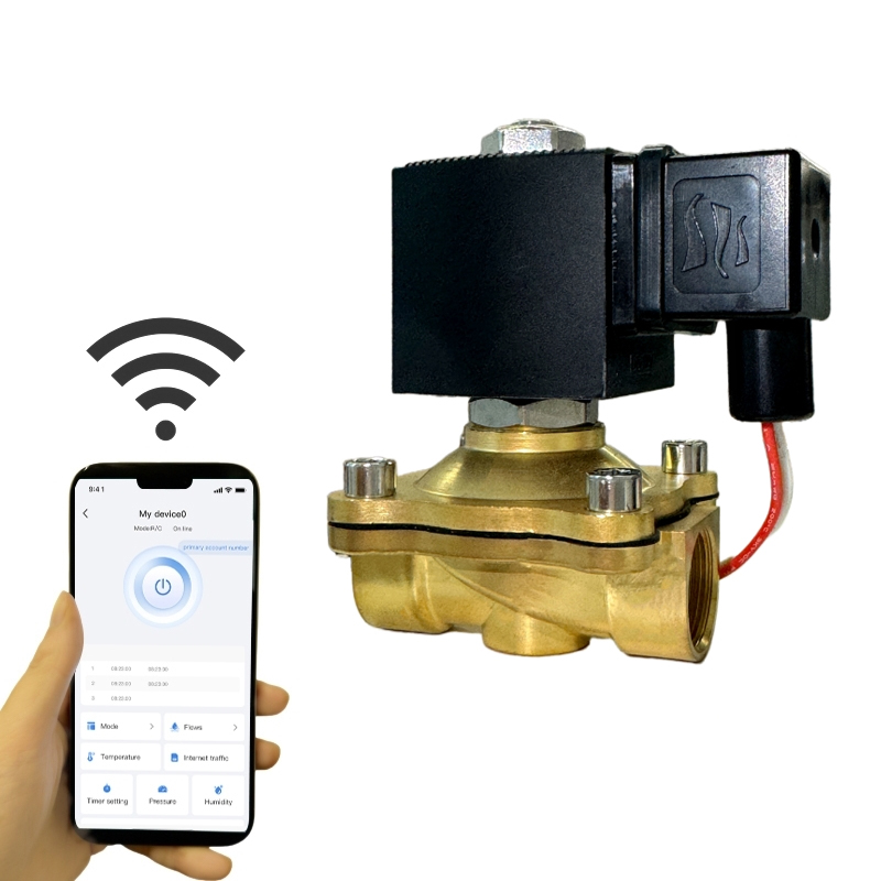
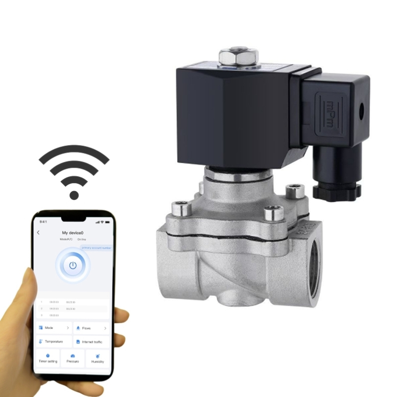
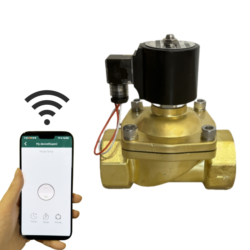
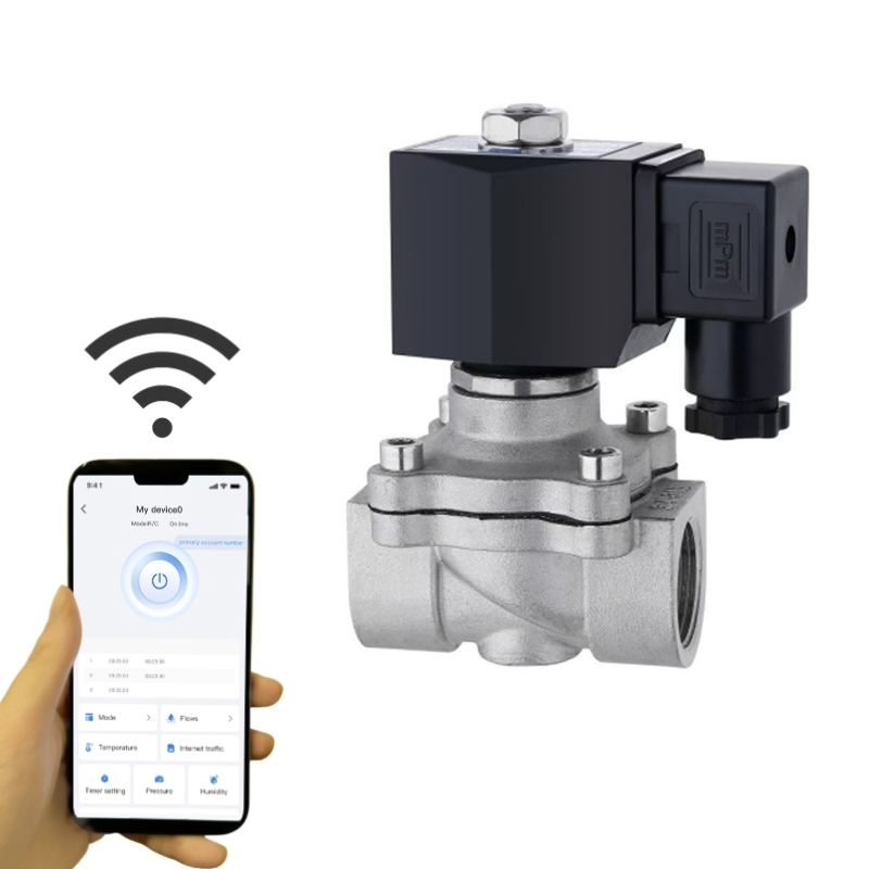
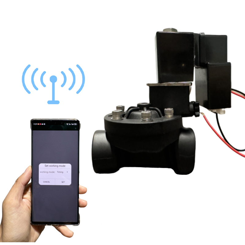
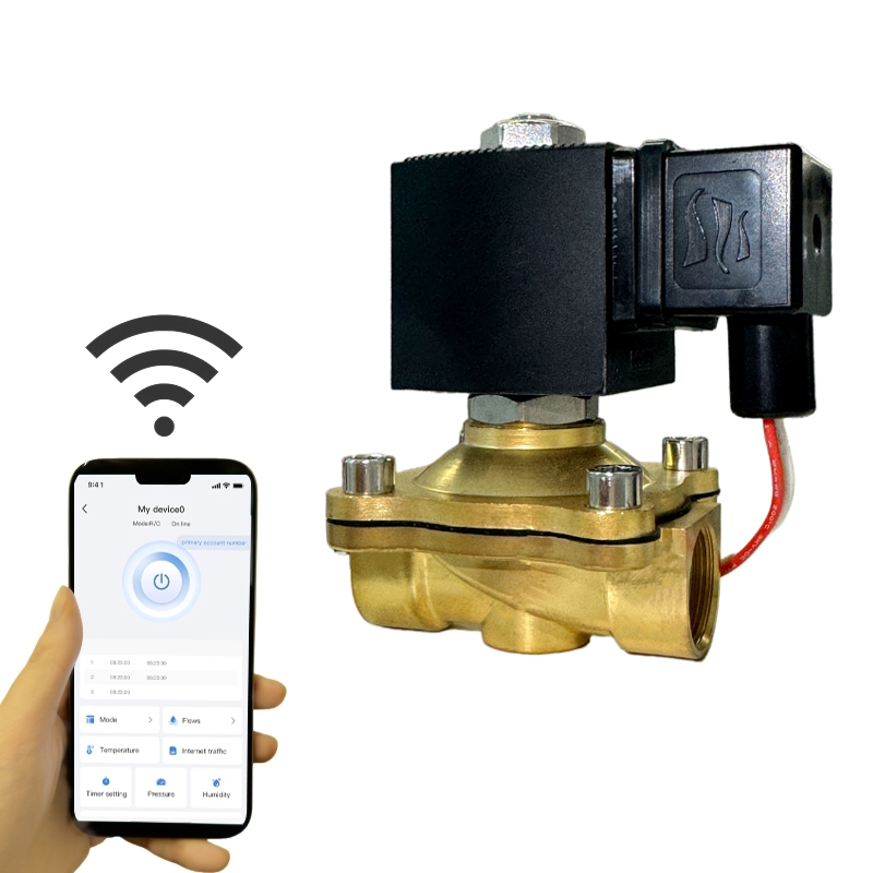
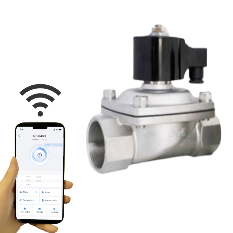
No rewiring, no external driver box needed — with brass or stainless-steel valve bodies that drop straight into existing standard valve installations. From day one, the electricity bill, the control cabinet temperature, and the power-supply parts list will tell the difference.



Copyright © 2025 Alahot (zhejiang) Technology Co., Ltd.
All Rights Reserved.
OEM/ODM Electric Solenoid Valves Manufacture
