


 English
 Español
News
Home / News / Solenoid Valve Solutions / Electric Solenoid Valves: How to Select, Size, and Install the Right Valve
News
Content
A 24 VDC coil rated at 5 W can hold a 100 bar stainless steel valve shut for months, and the same coil can burn out in three weeks when seal material, duty cycle, or minimum pressure differential was never checked. Electric solenoid valves sit at that intersection: a small electrical input, a plunger stroke measured in fractions of a millimeter, and a fluid line that punishes every mismatch. The specifications that decide whether a valve lasts five years or five days are all measurable, and almost all of them are fixed before the purchase order is signed.
An electric solenoid valve is an electromechanical shut-off device: current through a coil generates a magnetic field that strokes a plunger or a pilot diaphragm, opening or closing an orifice so flow starts and stops without a manual handle.
Core definition: a coil, a movable plunger, a sealing element, and either a return spring or a permanent magnet. Energizing the coil strokes the valve; de-energizing returns it to its fail-safe position.
Two-port valves handle on and off. Three-port valves divert flow or vent a line. Most irrigation, HVAC, and process circuits specify normally closed, so a power failure closes the valve instead of flooding a zone or draining a loop.
Four inputs should be fixed before ordering:
Circuit architecture, port configurations, and normally open versus normally closed logic are covered in more depth in this solenoid valve function and application guide.
Choose direct-acting when line pressure can fall to zero; choose pilot-operated when the line always holds a minimum differential and you want large flow from a small coil.
A direct-acting valve lifts the seal with coil force alone, so it works from 0 bar, tolerates viscous or lightly contaminated media better, and usually costs less in small sizes. The trade-off is scale: orifices typically sit between 1 mm and 15 mm, and coil power climbs to 8-20 W to overcome full line pressure.
A pilot-operated valve uses line pressure on a diaphragm or piston to amplify the stroke. Orifices of 13 mm to 50 mm become practical with a 5 W coil, but the design needs roughly 0.2 to 0.5 bar of differential to open and is far more sensitive to debris and air entrapment.
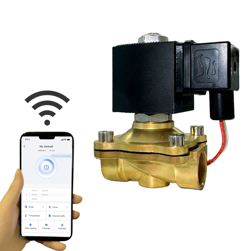
 Alahot 2W Series Brass Direct-Acting Solenoid ValveCompact brass direct-acting valve for liquid and gas control without pressure differential, useful where gravity-fed or empty-start lines rule out pilot-operated designs.View Product →
Field rule: if a line can drain, be gravity fed, or start empty, specify direct-acting even when the flow rate suggests a pilot-operated design.
Four numbers decide the majority of field failures: maximum working pressure, maximum media temperature, seal compatibility, and the flow coefficient the circuit actually requires.
The temperature limit of a valve is rarely the body. Coil insulation class sets the ambient ceiling, class F around 155 C and class H around 180 C, while the seal sets the media ceiling. A 150 C line needs FKM or PTFE seals no matter how robust the brass housing looks.
| Duty | Recommended architecture | Pressure band | Body material |
| Battery irrigation | Direct-acting latching | 0-10 bar | Nylon plastic or brass |
| Closed-loop HVAC water | Pilot-operated or motorized ball | 0.5-16 bar | Brass |
| Chemical dosing and acids | Direct-acting | 0-6 bar | UPVC, CPVC, or PTFE |
| Submerged fountain nozzles | Pilot-operated, IP68 | 0-10 bar | 304 stainless steel |
| High-pressure test rigs | Pilot-operated | 16-100 bar | 304 stainless steel |
After pressure and temperature, size on flow coefficient. Match the required Cv or Kv at the operating differential, not at the maximum rating, and add margin for fouling rather than for optimism.
Brass covers clean water and neutral media, 304 stainless covers aggressive or hygienic duties, and engineering plastics cover acids and chloride-rich chemical lines where dissolved metal ions are unacceptable.
Water, air, and neutral oil. Standard bodies hold 16 bar, high-pressure variants reach 50 bar. Avoid with ammonia, strong acids, and chloride-heavy chemistry.
Dilute acids, food and medical rinse water, hot water loops, and high-pressure circuits up to 100 bar. Performance still depends on the correct seal pairing.
Hypochlorite, acids, deionized water, and dosing lines. Pressure usually stays under 6 bar and the plastic body itself limits the temperature ceiling.
Seal first, body second: EPDM for water and dilute chemistry, FKM for oils and fuels, PTFE for solvents and hot aggressive media. Most leaks blamed on a body material began as a swollen or hardened seal.
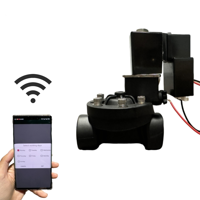
A standard coil draws 5 to 20 W continuously while energized, so battery, solar, and remote installations should specify a latching valve that holds position with a permanent magnet and consumes nothing once it has pulsed.
Latching designs are bistable: a 30 to 100 millisecond pulse moves the plunger and the magnet keeps it there until the next reversed pulse. Monostable latching versions add a spring return, which suits fire protection and safety circuits that must fail closed.
Standard coils are rated for 100 percent continuous duty inside their stated ambient range, and class F or H insulation handles that comfortably when the enclosure breathes. Sealed housings, high ambient heat, and constant energizing together are the usual cause of a burnt winding.
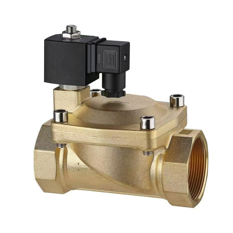 ALP Series 0.5W Low Power Brass Pilot Solenoid ValvePilot-operated brass valve with 0.5 W coil for medium- to high-flow systems, suited to battery, solar, or remote setups where power use matters.View Product →
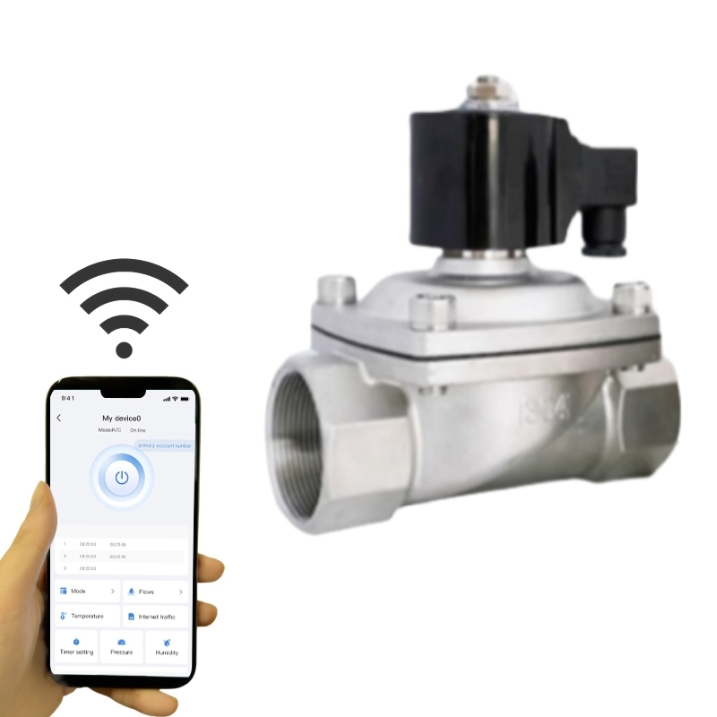
 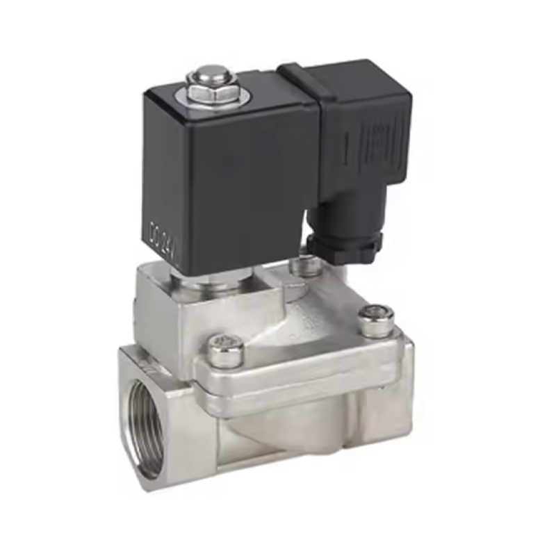 AL-LC Series Stainless Steel Latching Pulse Solenoid ValveSelf-holding SS304 pilot valve for short-time energizing and long-time actuation, useful for battery, solar, remote, or dust-removal flow control where low power matters.View Product →
Power arithmetic matters at scale: a 5 W coil energized continuously draws roughly 43.8 kWh over a year. The same circuit on a latching valve, pulsed twice a day, can drop below 1 kWh while delivering the same flow control.
Most first-year failures trace back to debris, wrong coil voltage, moisture at the connector, or over-torqued fittings rather than to the valve itself.
Fit a 100 mesh strainer upstream of every pilot-operated valve. One grain of sand sitting on a pilot orifice is enough to stop a diaphragm from seating, and the symptom looks exactly like a failed coil.
A solenoid valve strokes in 10 to 100 milliseconds and delivers on/off control at lower cost. A motorized valve takes seconds to travel and can stop at intermediate positions, which matters when a loop needs modulating flow rather than a simple open or closed state.
Only a direct-acting design can. Pilot-operated valves need roughly 0.2 to 0.5 bar of differential to lift the diaphragm, so gravity-fed lines, drained pipes, and start-empty circuits should use direct-acting or direct-acting latching valves.
Measure resistance across the terminals with power removed. A 24 VDC coil rated 5 to 10 W normally reads about 55 to 120 ohms; an open circuit or a very low reading indicates a burnt winding. Confirm with voltage measured under load, because a healthy coil can also fail to stroke on a weak supply.
A standard AC or DC coil draws 5 to 20 W continuously while energized. Latching and pulse versions use a short 30 to 100 millisecond pulse and then hold position mechanically, which is why they dominate battery irrigation, remote sites, and energy retrofit projects.
Pressure band, media and concentration, seal compound, coil voltage, and duty cycle are the five inputs that turn a vague request into a valve that survives commissioning week and the five years after it.
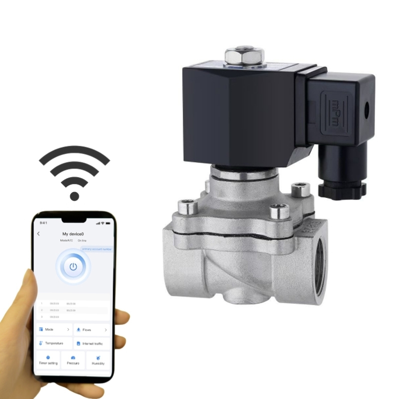
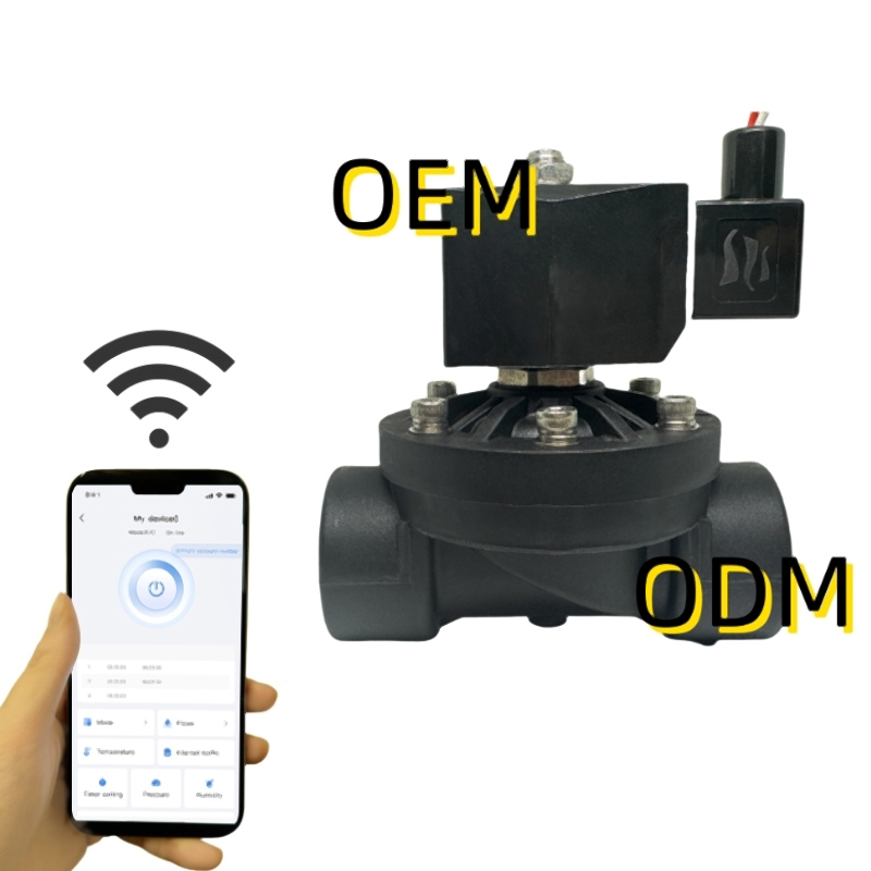
Alahot (Zhejiang) Technology builds electric solenoid valves as embedded control units rather than standalone fittings, from 1/8 inch miniature valves to 100 bar stainless steel bodies, with first samples typically ready in about two weeks and long-run design refinement measured in years.



Copyright © 2025 Alahot (zhejiang) Technology Co., Ltd.
All Rights Reserved.
OEM/ODM Electric Solenoid Valves Manufacture
