


 English
 Español
News
Home / News / Solenoid Valve Solutions / Latching Operated Solenoid Valves: Zero-Power Design, Selection and Sizing
News
Content
A standard 6 W solenoid valve energized eight hours a day uses roughly 17.5 kWh per valve per year, and on a battery or solar supply that figure decides the size of the panel and the battery. Latching operated solenoid valves remove the standing drain: one short current pulse moves the plunger, a permanent magnet holds it in place, and holding current drops to zero.
If you are specifying valves for a battery-powered irrigation controller, a remote water or gas line, a solar-fed fire skid, or a fountain panel fed from a small supply, the latching design is usually the first branch to evaluate. It changes the driver circuit, the coil winding, the cable gauge and the controller logic, not only the valve body.
A latching operated solenoid valve changes position when it receives a momentary current pulse and then stays in that position with no holding current, because a permanent magnet in the magnetic circuit keeps the plunger seated against the pole piece.
Definition. A latching solenoid valve is a pulse-actuated valve with a magnetically held position. The coil is energized only during the switching event, so the valve behaves as a memory element in the fluid circuit rather than as a continuously powered actuator.
A conventional direct-acting valve must keep its coil energized to hold the plunger against a return spring. That spring is what makes standard valves fail closed or fail open, and it is also what makes them expensive to run from a battery. The latching version replaces the spring hold with magnetic hold, so the coil works only for the few milliseconds it takes to move the plunger.
The trade-off is in the driver. Most single-coil bistable latching valves need a reverse-polarity pulse to return, which means an H-bridge, a polarity-reversing relay, or a capacitor discharge circuit. Two-coil and three-wire versions reset through a second winding and work with a simpler driver, at the cost of an extra conductor in the cable.
Choose bistable latching when the valve must hold either position indefinitely, and monostable latching when it must return to a defined position without a second pulse. That single decision sets the coil wiring, the driver architecture and the failure behaviour of the whole control loop.
| Property | Bistable latching | Monostable latching |
| Rest state | Holds the last commanded position | Returns to one defined position |
| Reset method | Reverse polarity pulse or second coil | Spring, hydraulic decay or internal timer |
| Driver requirement | H-bridge or polarity-reversing relay | Single-ended driver, fixed polarity |
| Energy per full cycle | Two pulses | One pulse |
| Behaviour on power loss | Stays where it is | Returns to the rest position |
| Typical duty | Battery irrigation, remote shutoff, gas lines | Timed flush, self-closing taps, dosing |
Latching valves win wherever a valve stays in one state for hours or days and electrical power is scarce; they lose wherever the valve must modulate, cycle quickly, or fall into a safe position when the supply disappears.
Purchase check. Ask for four numbers before you design the driver: coil resistance, rated pulse voltage, minimum pulse width at that voltage, and energy per actuation in millijoules. A supplier who cannot state all four cannot help you size the battery or the discharge capacitor, and you will discover the gap during commissioning.
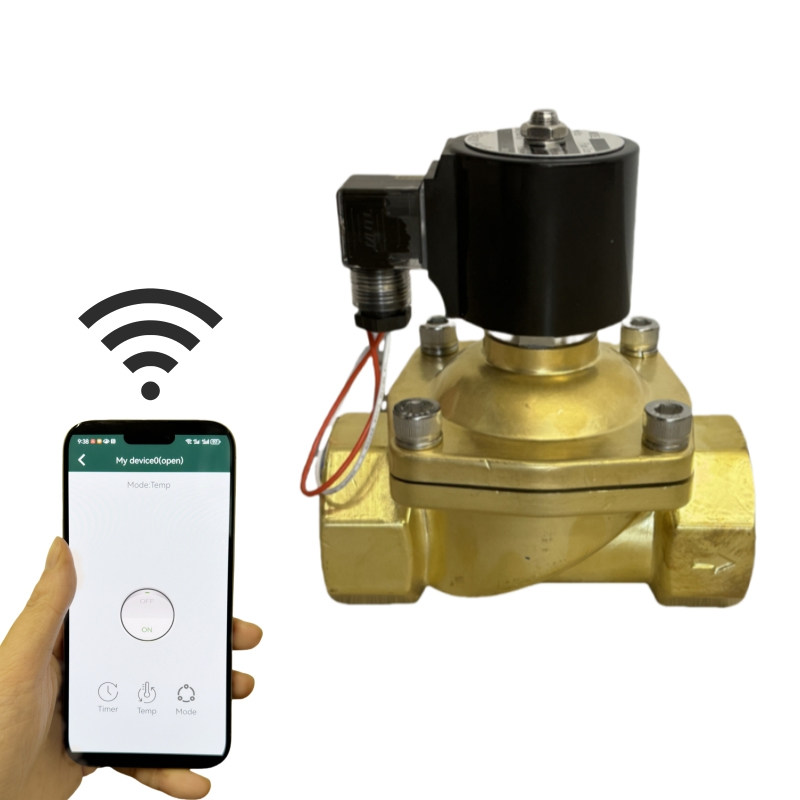
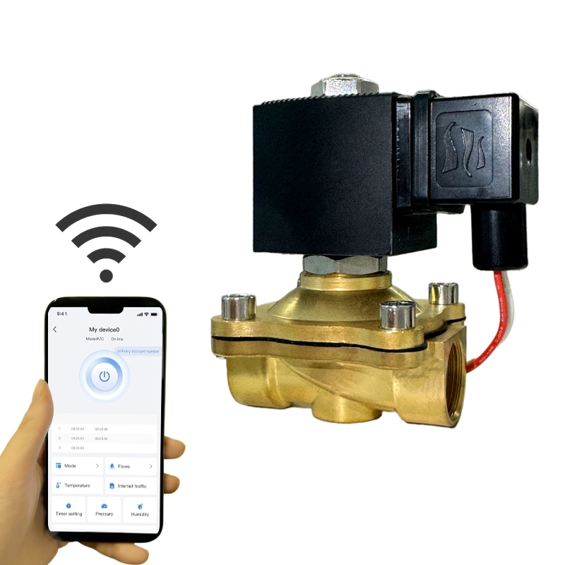
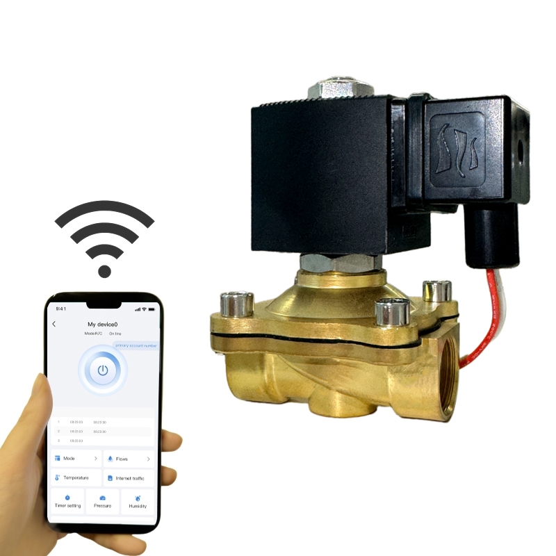
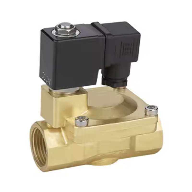 Brass AL-LC Pulse Latching Solenoid ValveReview the brass AL-LC pulse/latching valve for low-power auto-reset operation, standard DIN43650 connection, and DC 3.3 V minimum voltage when sizing driver and pressure requirements.View Product →
Sizing a latching valve starts with the differential pressure the plunger must overcome, not with the pipe diameter, and it ends with the coil parameters that your controller can actually deliver.
Direct-acting latching valves open from zero differential, which is why they dominate battery irrigation and dosing lines. Pilot-operated versions need roughly 0.5 to 1 bar to open reliably but pass far more flow per coil watt, so they suit larger lines with stable upstream pressure.
Brass covers water and neutral media up to about 16 bar. Stainless steel 304 suits potable water, higher temperatures and mildly corrosive fluids. Reinforced nylon, UPVC, CPVC and PTFE handle acids, brine and chlorine where any metal in the wetted path would corrode.
Battery and solar controllers usually supply 9 to 12 V DC; industrial panels typically use 24 V DC or rectified AC. Read coil resistance and minimum pulse width together, because a lower resistance coil needs a stronger driver but a shorter pulse.
Confirm how the valve returns: reverse polarity from an H-bridge, a second coil, or spring assistance. Test the complete loop on the bench with the real cable length before the valve goes into the ground.
A coil that draws 0.5 A at 12 V for 50 ms consumes about 0.3 J per actuation. Two actuations a day for an entire irrigation season stays well under one watt-hour, which is why latching valves have become the default choice for solar and battery fluid control.
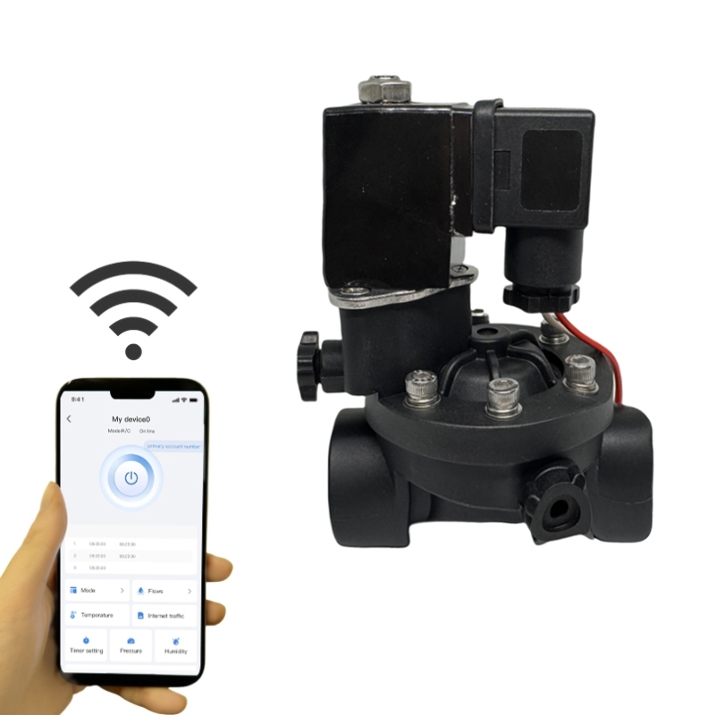
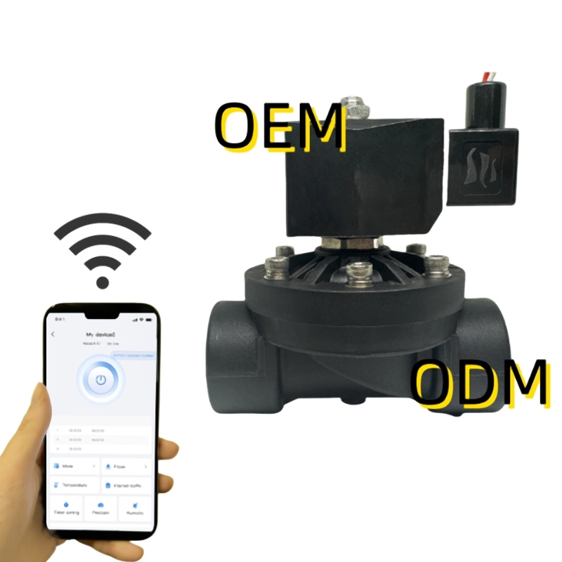
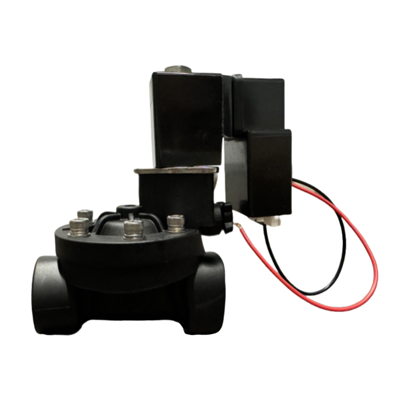 Plastic AL Series Latching Solenoid ValveConsider this plastic AL-series latching valve for battery or solar fluid control; its integrated driver and DIN43650 interface simplify low-power pulsing and field wiring checks.View Product →
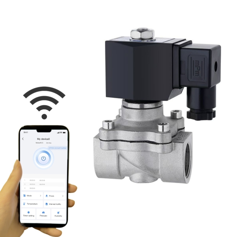
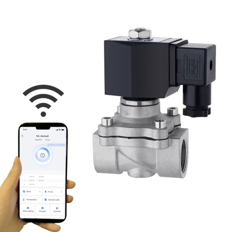
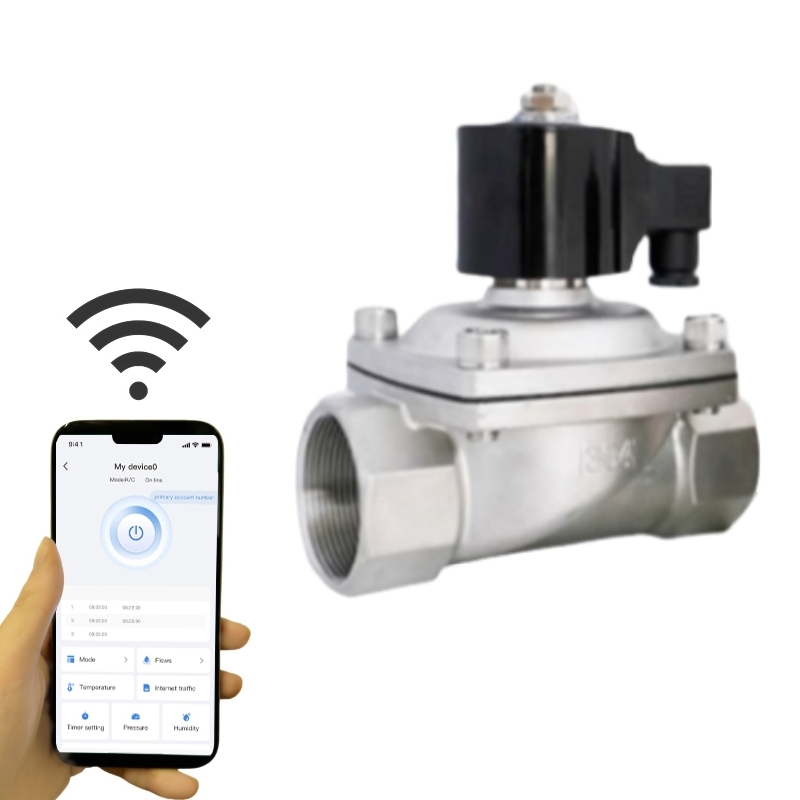
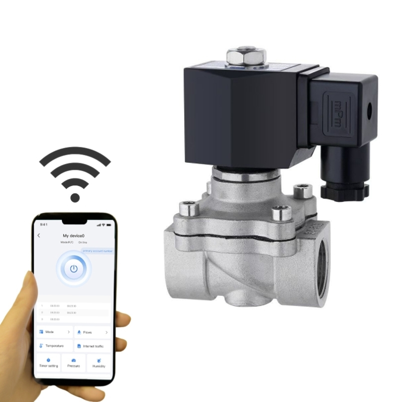
 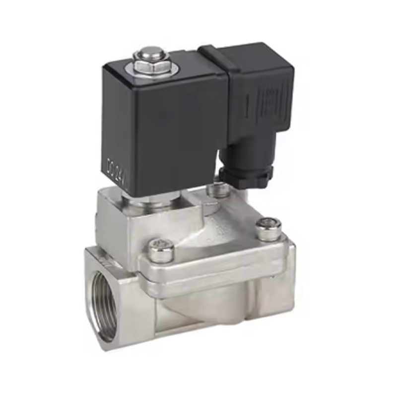 Stainless Steel Pulse Latching Solenoid ValveReview this SS304 pulse/latching valve for low-power dust collection or irrigation control, where short energizing and SS304 construction suit remote battery-powered installations.View Product →
Most latching valve complaints in the field trace back to the driver, the wiring or the pulse timing rather than to the valve body itself, so work through the electrical path before you open the valve.
Field reference. A short diagnostic walkthrough of the six failures we see most often on latching valves, including driver faults and stuck plungers, is collected in these latching solenoid valve troubleshooting notes, which map each symptom to a measurement you can take on site.
A standard solenoid valve needs continuous current to hold its open position, while a latching valve uses a permanent magnet to hold position after a pulse of roughly 30 to 100 ms. Holding power falls to zero, but the controller must be able to deliver a defined pulse rather than a steady output.
Use the minimum pulse width stated for the coil at your supply voltage, plus a small margin for cable voltage drop. Lengthening the pulse beyond what the datasheet requires does not make the valve switch more reliably; it only heats the winding.
Only if the valve is a two-coil or three-wire type, where a common line plus one switched conductor per direction does the work. Single-coil bistable valves need polarity reversal, which means an H-bridge, a reversing relay, or a capacitor discharge circuit in the controller.
They stay in the last commanded position, which is predictable but not fail-safe. Where a guaranteed closed position matters, choose a spring-return monostable latching design or a standard normally closed valve instead.
If the four coil numbers are still missing from your specification, that is the gap worth closing first. Review the full latching and pulse solenoid valve range to compare brass, plastic and stainless steel options by pulse voltage, coil resistance, orifice size and sealing class before you commit the driver design.



Copyright © 2025 Alahot (zhejiang) Technology Co., Ltd.
All Rights Reserved.
OEM/ODM Electric Solenoid Valves Manufacture
