

 English
 Español
News
Solenoid Valve Solutions
How to Test a Solenoid Valve: Step-by-Step Guide
Content
- 1 The Quick Answer: How to Test a Solenoid Valve
- 2 Tools You Need Before Starting
- 3 Step-by-Step: Testing with a Multimeter
- 4 Testing a Solenoid Valve Without a Multimeter
- 5 Common Solenoid Valve Faults and How to Distinguish Them
- 6 Testing Solenoid Valves in Specific Applications
- 7 Safety Precautions When Testing Solenoid Valves
- 8 When to Replace vs. Repair a Solenoid Valve
The Quick Answer: How to Test a Solenoid Valve
To test a solenoid valve, use a multimeter to check coil resistance and apply direct voltage to confirm mechanical operation. A healthy solenoid coil typically reads between 10–100 ohms depending on the valve design, and the valve should click audibly when energized. If resistance reads 0 ohms (short) or OL/infinite (open circuit), the coil has failed. If resistance is normal but the valve doesn't open or close, the mechanical plunger or seat is at fault.
Testing takes less than 10 minutes with basic tools and can save you from unnecessarily replacing an entire assembly when only one component has failed.
Tools You Need Before Starting
Gather these before you begin — having the right tools prevents guesswork and speeds up diagnosis:
- Digital multimeter (DMM) — for resistance and voltage readings
- Appropriate power source — matches the valve's rated voltage (e.g., 12V DC, 24V AC, 120V AC)
- Insulated jumper wires or test leads
- Safety gloves (especially for 120V AC systems)
- Valve datasheet or nameplate data (for rated voltage and coil resistance specs)
Check the valve's label or manufacturer spec sheet for the nominal coil resistance value. This is your target when performing resistance tests.
Step-by-Step: Testing with a Multimeter
Step 1 — Disconnect Power and Isolate the Valve
Always de-energize the circuit before connecting your multimeter probes. Shut off the power supply and, if applicable, close the upstream fluid or air supply to prevent unexpected actuation. Disconnect the coil wiring from the control circuit so you're measuring only the coil — not the rest of the system.
Step 2 — Measure Coil Resistance (Ohms Test)
Set your multimeter to the resistance (Ω) mode. Touch the probes to the two coil terminals.
| Reading | What It Means | Action |
|---|---|---|
| Within spec range (e.g., 20–60 Ω) | Coil is electrically healthy | Proceed to functional test |
| 0 Ω or near 0 | Short circuit in the coil winding | Replace the coil |
| OL / ∞ (infinite) | Open circuit — broken wire or burnt coil | Replace the coil |
| Far outside spec (e.g., 5× higher) | Degraded winding, possible overheating damage | Replace the coil |
As a real-world example: a 24V DC solenoid from ASCO typically reads around 29–32 ohms. A 12V automotive solenoid may read as low as 8–12 ohms. Always compare against the manufacturer's spec, not a generic rule.
Step 3 — Perform a Voltage Test While Energized
Switch your multimeter to AC or DC voltage mode (matching your system). Reconnect the coil wiring and power the circuit. Measure voltage across the coil terminals while it should be energized. You should see a voltage reading close to the rated voltage (within 10%). If voltage is correct but the valve doesn't actuate, the problem is mechanical, not electrical.
Step 4 — Apply Direct Power for a Functional Test
Bypass the control circuit entirely and apply rated voltage directly to the coil terminals using jumper wires. Listen for a clear, sharp click — this is the plunger moving. If you hear a click, the coil and plunger are working. If there's a buzz or hum but no click, the plunger may be stuck. If there's silence, the coil is not activating. With the fluid/air supply connected, check for flow when energized and cessation of flow when de-energized (for normally closed valves).
Testing a Solenoid Valve Without a Multimeter
If you don't have a multimeter on hand, you can still perform a basic functional test:
- Listen test: Apply rated voltage directly to the coil. A working solenoid produces a distinct click. No sound indicates an electrical fault; buzzing indicates a mechanical jam.
- Touch test (low-voltage DC only): On 12V or 24V DC systems, briefly touch the coil housing after energizing. A coil that's warm-to-hot after a few seconds is drawing current and working. A coil that stays cold isn't energizing at all (open circuit).
- Flow test: If the valve is plumbed in, open the upstream supply and energize the valve. Observe whether flow starts or stops as expected. This is a pass/fail test for the whole valve rather than diagnosing which component failed.
These methods can confirm obvious failures but won't identify borderline coil degradation that a resistance test would catch early.
Common Solenoid Valve Faults and How to Distinguish Them
Understanding failure modes helps you test more efficiently and avoid misdiagnosis:
| Fault | Symptom | Resistance Test | Functional Test |
|---|---|---|---|
| Burnt/open coil | No response at all | OL / infinite | No click, no flow change |
| Shorted coil | Overheating, blown fuse | 0 Ω or near 0 | May click but draws excess current |
| Stuck plunger | Buzzing without actuation | Normal | Buzz but no click or flow change |
| Contaminated seat/seal | Leaking when closed | Normal | Clicks normally, but leaks |
| Insufficient supply voltage | Intermittent operation | Normal | Works on direct power, fails in circuit |
Stuck Plunger: Mechanical Cleaning vs. Replacement
A stuck plunger is one of the most common mechanical failures, especially in water or wastewater applications. Mineral deposits and debris are frequent culprits. In many valve designs, the coil can be removed and the plunger assembly accessed for cleaning with compressed air and a light solvent. If cleaning doesn't restore free movement, replace the plunger sleeve assembly — not necessarily the entire valve body.
Testing Solenoid Valves in Specific Applications
HVAC and Refrigeration Systems
Refrigerant solenoid valves typically operate on 24V AC. Use an AC voltmeter to verify supply voltage at the coil during a call for cooling or heating. Resistance of common refrigerant valves often falls in the 13–30 ohm range. A valve that opens but doesn't fully seat on de-energization usually has a worn or cracked seal rather than an electrical fault.
Irrigation Systems
Irrigation solenoids run on 24V AC from the controller. Test resistance at the valve wiring (after disconnecting from the controller). Values above 100 ohms or OL indicate a failed coil. Also check wiring resistance from the controller box to the valve; long wire runs with corroded connections can add enough resistance to prevent full actuation even with a healthy coil.
Automotive Applications
Automotive solenoids (transmission shift solenoids, VVT solenoids, fuel injectors) operate on 12V DC. Resistance specs are tighter — a transmission shift solenoid typically reads 11–15 ohms. Use a scan tool alongside the multimeter when testing in-vehicle, as many automotive solenoids are PWM-controlled and may show correct resistance but fail under duty-cycle loads. Always check the vehicle-specific service data for acceptable resistance ranges.
Pneumatic and Hydraulic Systems
Industrial pneumatic valves often use 24V DC or 120V AC coils. After confirming coil resistance, perform a functional test using a regulated air supply at the rated pressure (commonly 80–100 PSI for pneumatics). A valve that clicks and moves the plunger but doesn't shift airflow may have a worn or cracked valve seat that requires a rebuild kit rather than a new valve.
Safety Precautions When Testing Solenoid Valves
- Never apply voltage higher than the rated coil voltage. Even briefly exceeding the rating can burn out a coil instantly.
- For 120V AC or 240V AC systems, use insulated probes and keep one hand away from the circuit to prevent current flowing across your chest.
- Relieve system pressure before disconnecting any valve in a pressurized fluid or gas line.
- Don't hold a solenoid coil energized for more than a few seconds during testing unless the coil is rated for continuous duty — intermittent-duty coils can overheat quickly without fluid flow to dissipate heat.
- In hazardous or explosive environments, use only intrinsically safe test equipment rated for the zone classification.
When to Replace vs. Repair a Solenoid Valve
Testing tells you what failed — here's how to decide what to do next:
- Failed coil only: Most valves have a replaceable coil that slides off the valve body. Replacement coils typically cost $10–$50 versus $50–$300+ for a complete valve. Always replace just the coil first.
- Stuck or worn plunger: Rebuild kits including the plunger, spring, and seals are available for most industrial and irrigation valves. If the valve body threads are in good shape, a rebuild makes economic sense.
- Cracked or corroded body: Replace the entire valve. Attempting to seal a cracked body is a short-term fix that creates a leak hazard.
- Multiple failures or repeated reoccurrence: Evaluate whether the valve is correctly specified for the application — wrong pressure rating, incompatible fluid, or wrong duty cycle causes premature wear regardless of how many times you repair it.
Our Main Products


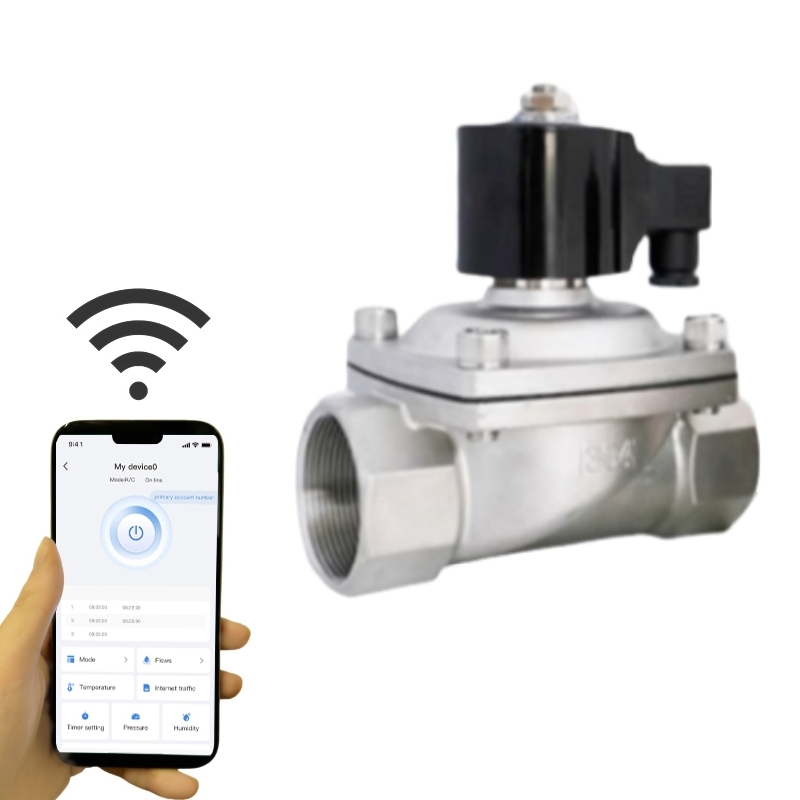
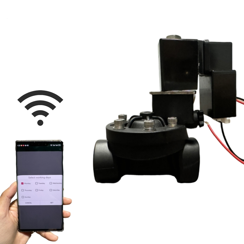
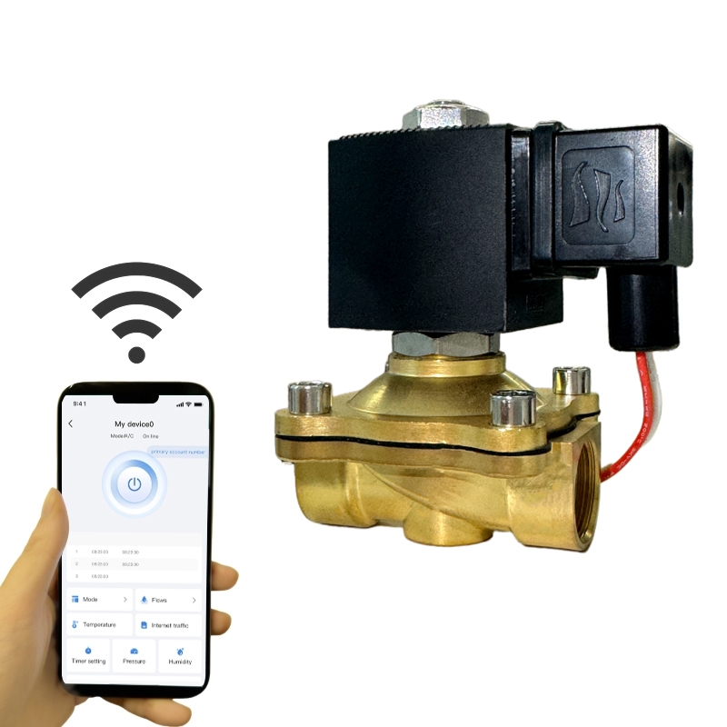

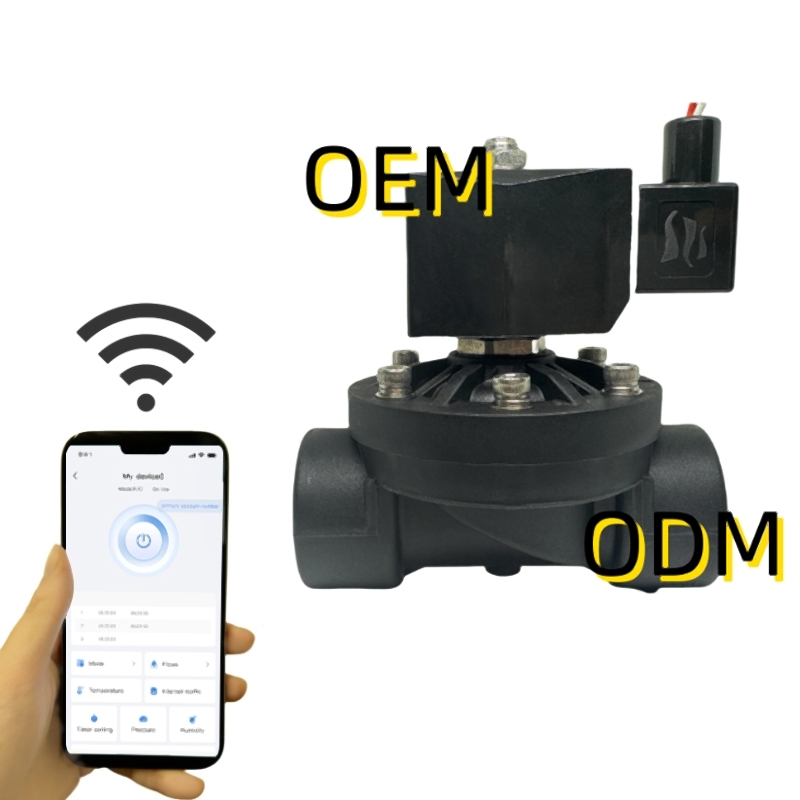
Alahot is Water Solenoid Valves Manufacturer and Factory in China. Follow our social media postings for the latest news and exhibitions.
Discover
Contact
-
 3/F, No.72 Desheng Lane, Gongshu District, Hangzhou, Zhejiang, China
 -

-
 +86-18768178590
Newsletter
Copyright © 2025 Alahot (zhejiang) Technology Co., Ltd.
All Rights Reserved.
OEM/ODM Electric Solenoid Valves Manufacture
